The below figure shows four D-type flip-flops connected as a shift register using a XOR gate. The initial state and three subsequent states for three clock pulses are also given.
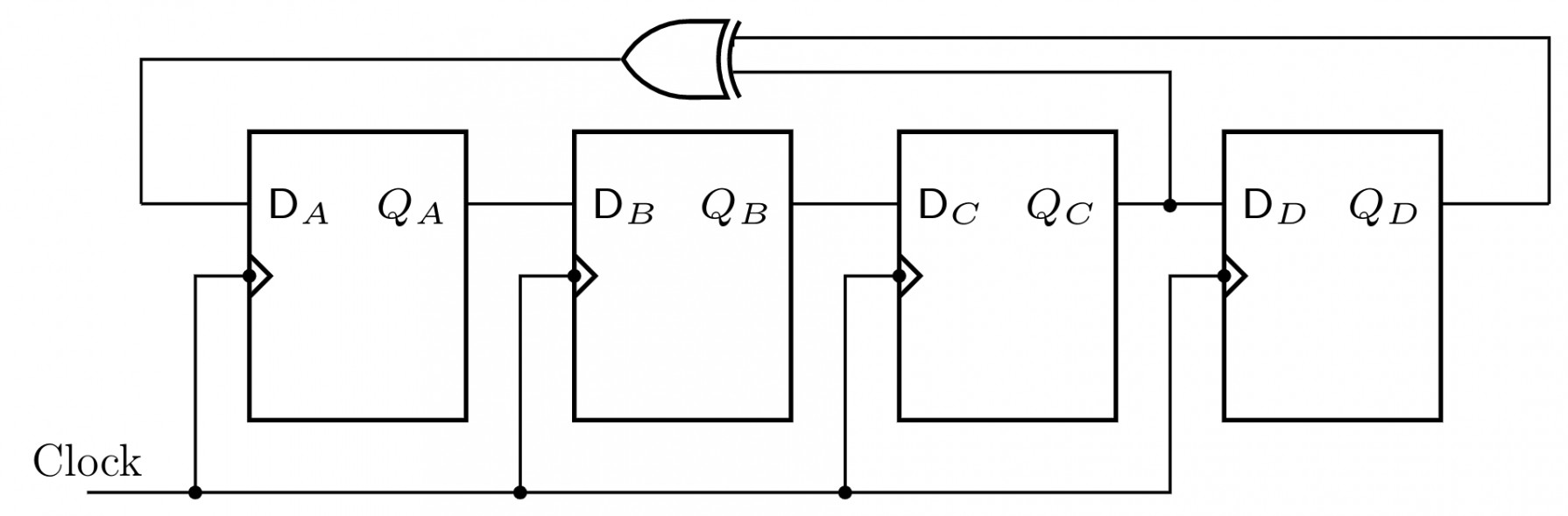
StateInitialAfter the first clockAfter the second clockAfter the third clockQA1000QB1100QC1110QD1111
The state QAQBQCQD after the fourth clock pulse is